[3DModelWindow] | |
Edit Mode/ Pick Open Edge |
Specify the edge to open when unfolding. The way of selecting changes depending on [Edge Pick Mode]. |
---|---|
Edit Mode/ Divide Edges and Make Them Smooth (-> detail) |
Make the surface of 3D model smooth by dividing specified edges. |
Edit Mode/ Edit Model (-> detail) |
Edit model. Simple commands are provided. |
Edge Pick Mode/ Pick Single Edge |
Pick edges one by one by clicking on them. The selected edges are colored in orange. If you click again, the edge is deselected. |
Edge Pick Mode/ Specify Shortest Path between Two Points |
Pick two vertices and the edges on the shortest path between them become selected. |
Pick Symmetrical Edge | When this option is on, the edge located on the symmetrical position of selected edge is selected at the same time. |
Reset Edge Type | Resets status of the edge that the user specified to open. |
Turn On Light |
Turns on a virtual light in the 3D window. The model is rendered as being
lit and it becomes easy to recognize the 3D model.
|
Show Faces | Shows the faces on the 3D model. When this option is off,
the model is rendered as a wire frame model. * Usually turn this option on. |
Show Edges | Shows the edges of the 3D model. * Usually turn this option on. |
Reset Model View | Resets position, direction, and zoom of the 3D model to the default model state. |
Display Setting (-> detail) |
Set the configurations of 3D model window. |
Show Object List
(-> detail) |
Opens a dialog which shows an object name list of the
objects included in the model. You can switch between showing and hiding
each object. Only objects shown are involved in the creation of the development. |
Change Coordinates/ Change Model Coordinates (-> detail) |
Change coordinates of 3D model by 4 steps. |
Change Coordinates/ Flip U-coordinate of Texture |
Flip U-coordinate of Texture. |
Change Coordinates/ Flip V-coordinate of Texture |
Flip V-coordinate of Texture. |
Change Coordinates/Flip Faces | Invert the direction of faces. |
Change Coordinates (-> detail) |
Starts the wizard for adjusting the model's coordinates. |
Join Adjacent Isolated Edges |
Joins all the adjacent isolated edges. The development might become separated, because, sometimes a 3D model's faces look connected, but in fact they aren't joined. When there are such faces, this feature allows you to connect all the adjacent isolated edges and to join all the adjacent faces. The faces to be connected need to be included in the same object. |
Edit Mode / Divide Edges and Make Them Smooth | |
![]() |
[Go] After selecting edges, push the [Go] button to divide the edges and make them smooth. (Click edges again or select [3DModelWindow]-[ Reset Edge Type] to reset the selected edges. The selected edges have to be connected. An isolated edge does not generate any changes.) [Close] Closes the dialog. [Import open edges] Import edges specified to open for division of edges. [Details] Shows detailed options. [Divide limit] The value of minimal length of the division of edges relative to model size. When the value is smaller, edges are divided into smaller edges. [Smooth limit] The value of the limit angle for the edge-swap operation. Smooth operation swaps the edges so that the model becomes smooth, but when an angle of a edge is smaller than this, the edge swap is not applied. Usually specify between 90-100 degrees. * The left image is a dialog showing the detailed options. |
Edit Mode / Model Edit | |
![]() |
[Move Vertex] Moves vertices and edits the figure of the model. Drag the top of the red, blue and green arrows that appear to move the selected vertex. [Swap Edge] Swaps edges by selecting them. ![]() [Delete Edge] Deletes edges by selecting them. As the result, associated faces are also removed. (Only deletable edges can be selected) [Divide Edge] Divides edges by selecting them. One edge is divided into two at the center of the edge. As the result, associated faces are also divided. [Split Quad] Splits a quad polygon into two triangles by selecting them. |
Display Setting | |
![]() |
[Face] Set the way of rendering of faces. Normally [Color & Texture] is selected. [White] renders faces with white color. [Edge] Set the way of rendering of edges. [Color] option sets different colors to edges according to the type; mountain, valley, and cut. [Light] Render the model with light. [Size of Opening(after fold)] Specify the degree of opening of 3D model. [View Angle] Sets the degree of perspective. [Reset] Resets the options of this dialog. |
Show Object List | |
![]() |
[Object List] List of all object's file names. Switch between show/hide by clicking the name. Only selected objects become targets for unfolding. [Select All] Selects all objects in the list. [Clear] Deselects all objects in the list. |
Change Coordinates | |
![]() |
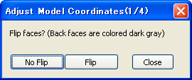
[Step1] Define the normal direction of the faces. [Close] end this wizard. |
![]() |
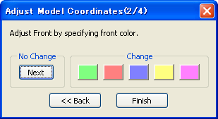
[Step2] Define the front by selecting the appropriate color button. |
![]() |
[Step3] Define the bottom by selecting the appropriate color button. |
![]() |
[Step4] Specify whether or not to invert the model. This wizard can be called whenever you want by selecting [3DModelWindow]-[Change Coordinates]. |